Akin’s 9th law:
Not having all the information you need is never a satisfactory excuse for not starting the analysis.
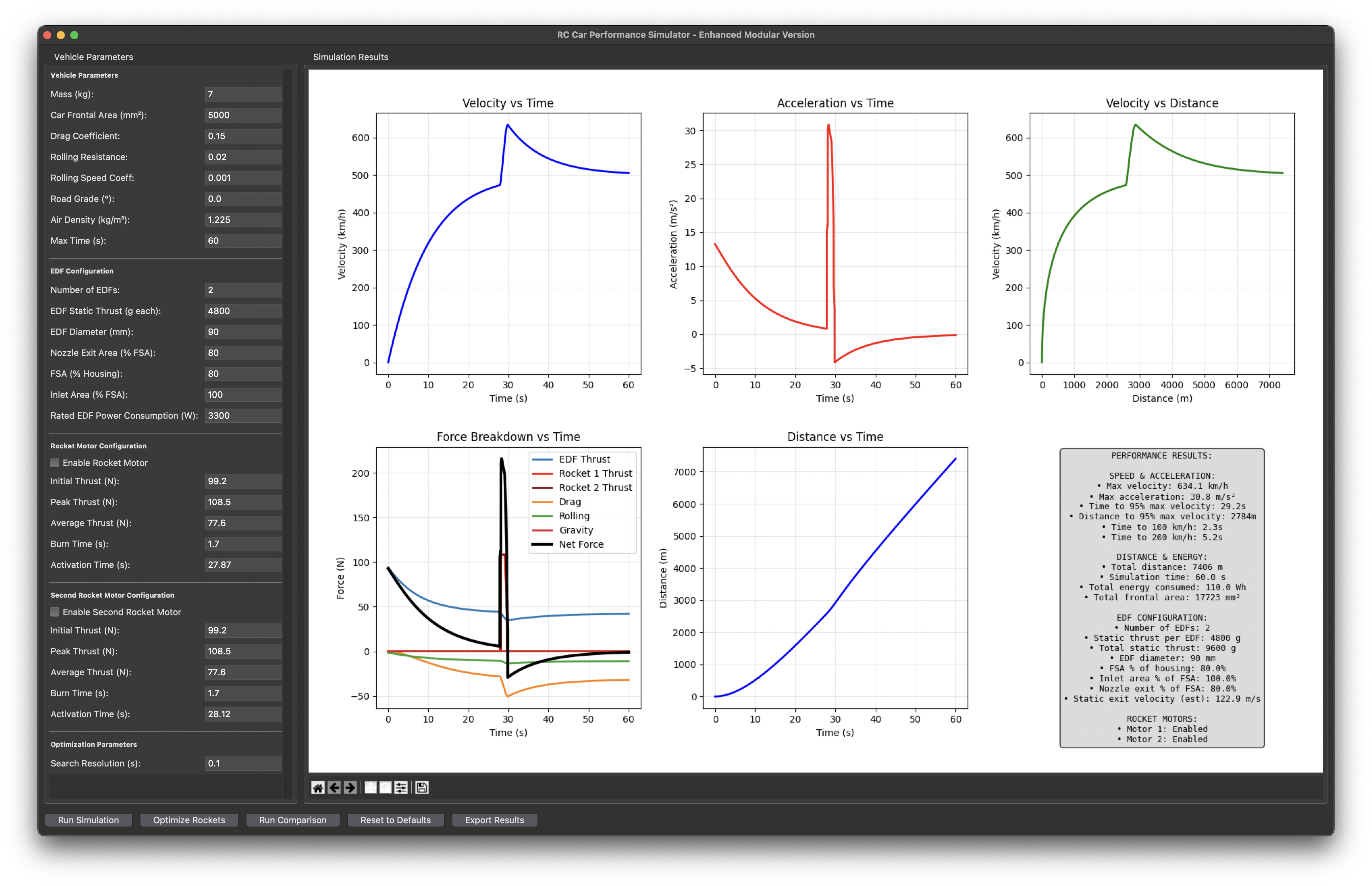
Making the world’s fastest RC car is a lofty goal, and it would be embarrassing to build a car based on vibes that comes nowhere close to breaking the record. To drive confidence in this idea, I decided to make a program that would simulate a straight-line top speed run given basic vehicle parameters. This program is written in Python and utilizes a basic road loads model combined with a fan model based upon momentum theory.
How Fast Does it Go?
Some caveats before we begin. Firstly, the adage of “all simulations are wrong, some are useful” definitely applies here. This simulator makes a ton of assumptions and relies upon limited information that is given for most off the shelf fans. As design is an iterative process, I can always go back and refine this simulator with any testing results I get later on. Secondly, the vehicle parameters input in the model are based upon using a pair of 90mm FMS EDF units, two Aerotech G80-T rocket motors, and a whole lot of guessing for everything else. As I get further into the design process I will refine these parameters to get a better idea of how the car will actually perform.
Results without Rocket Motors
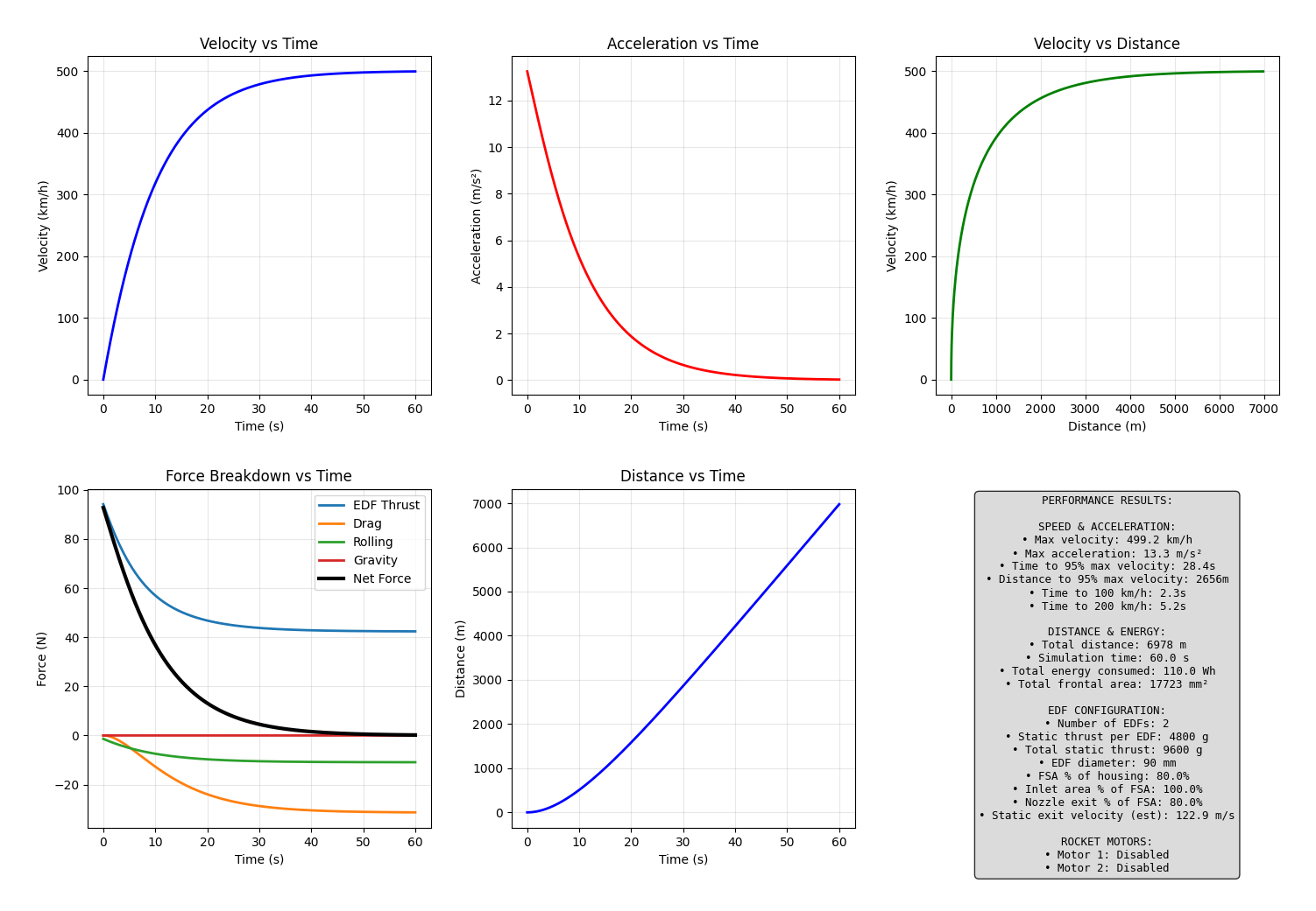
With a top speed of almost 500 kph (310 mph) this design beats my 400 kph (250 mph) target top speed comfortably without the use of rocket motors. Unfortunately, it takes about 3 kilometers (1.9 miles) to get there. Finding a road of this length will be a challenge, but even at a mile I’m comfortably above my goal. Let’s call this cushion a “safety factor”.
Results with Rocket Motors
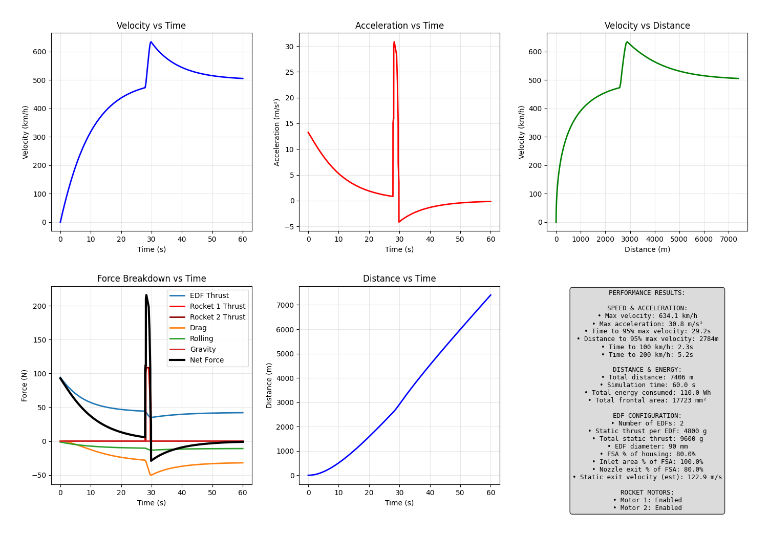
If my previous safety factor isn’t enough, this surely will be enough with a top speed of 635 kph (395 mph). Figuring out when to fire the rockets isn’t immediately obvious, so I also added a tool that will find the optimal time to light the rockets that maximizes the top speed of the vehicle. In reality, I will probably be space limited, so I will need to optimize around finding the firing time that maximizes the top speed within a set distance.
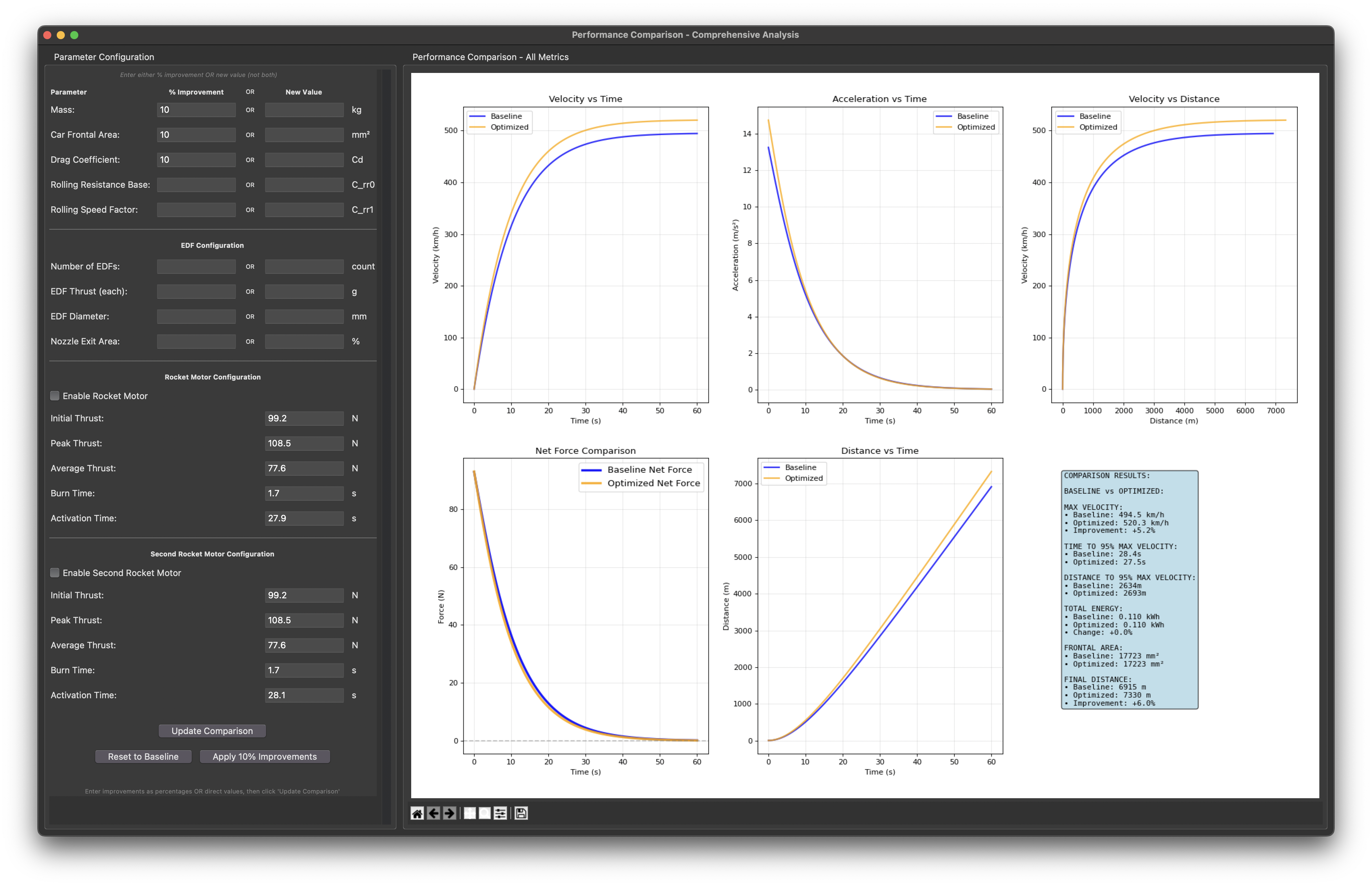
This comparison tool will be very helpful in design to understand the trade-offs between different components and designs on the performance of the vehicle. This example shows that a 10 percent improvement in mass, frontal area, and drag coefficient will increase the top speed by a little over 5 percent.
What are road loads?
Road loads are simply all of the forces acting upon a vehicle in motion. The main loads that need to be modeled are the propulsion system loads, aerodynamic loads, drivetrain loads, and gravitational loads. Road load models are the first step automotive engineers use to size powertrains, estimate energy usage (fuel economy, range, etc.), and to estimate basic performance attributes. I strongly believe that every automotive journalist should have to pass a test over the basic relationships of road loads and how they affect vehicle performance, I’m really tired of reading borderline misinformation in large car magazines.
Here are the road load relationships that I believe are the most critical to understand:
- Power is force multiplied by velocity
- Aerodynamic force increases with the square of velocity, the power to overcome aerodynamic drag increases with the cube of velocity
- Drivetrain losses mostly increase linearly with speed and most people don’t bother with advanced models for these forces
- Powertrain modeling is hard (especially with those Rube Goldberg machines we call internal combustion engines)
Fan Modeling
I’ve been down quite the rabbit hole when it comes to modeling fans. My initial confidence in embarking on this project stemmed from having a poor understanding of how fans work. Initially, I assumed that the quoted “static” thrust of the fans would be constant across all inlet velocities. This isn’t true and I ended up with napkin math telling me that I could easily break the sound barrier with a big enough fan. When I realized that air is stuff again, I was forced to reopen the text books from my least favorite classes.
I landed on using momentum theory and a (probably wrong) assumption that air power will be constant. I didn’t model fan rpm variation as a function of vehicle speed, transient behavior, and I assumed perfect ducting.
On “Vibe-Coding”
I’m a Mechanical Engineer by “training”, which while a pretty well rounded discipline it did not teach me how to do the vast majority of the programming required to do this project. So I used this project (and this website) as an opportunity to explore the new LLM based coding tools that are now available. For this project I used Visual Studio Code with the Github Copilot extensions to help develop this project. Without these tools, this simulator would be more of a command line based “script” than a “program” with a GUI. LLM caveats definitely apply here, you can’t blindly trust the outputs.
I’m well aware of the societal and environmental downsides of these technologies and I honestly don’t have a good excuse to justify why I use them in spite of these downsides. But I also don’t have a good excuse for eating meat or taking long hot showers.
Final Thoughts and Next Steps
I’ve spent probably way too long developing this simulator, but I learned a ton and I don’t feel like it was a complete waste of time. If anyone wants to run the program themselves, shoot me an email ([email protected]) and I’ll add you to the GitHub repo. I’m hesitant to make it completely public, because I want to make sure its accurate and a little more user friendly.
My next post will be about the component selection process for this car and also some sketches of what the car looks like in my head.


